27 March 2016
Short hiatus
I'm taking a short break from this project as other things that I have been neglecting start to assert themselves. Hope to get back to it early in April. Don't go away!
23 March 2016
SPI woes
I've been quite busy with other things recently so there hasn't been significant progress for a few days but I do have a few notes of potential interest to share.
I made a start on integrating the display, multiplexer and encoder software into a single executable running on one processor.
Immediately I ran into a quite unexpected problem! The Arduino has a high speed Serial Peripheral Interface (SPI), which permits cooperating devices to share a bidirectional port. Each device is supposed to request service by asserting a hardware select line. Well it doesn't work!
I have three devices that need to access the SPI.
I'm getting some assistance on the Arduino forum but so far there is no obvious solution in sight.
Meanwhile, I've returned to my dual Arduino solution, this time using the second Arduino merely as a display processor. It's quite easy to implement a byte-wide parallel interface between the two microcomputers, using 8 data pins and data available/ready lines to handshake byte movement across the interface. A simple protocol to package the display data into a data stream for transmission is straightforward as well.
So that's what I've done. And it works very well. Complete with handshaking I am seeing single byte transfer times around 22us and a typical packet of 12 bytes (a VFO frequency change update) takes 250us to transfer. That's more than adequate.
I still have to implement data transfer in the opposite direction. It's not even slightly demanding, as the only traffic is touch screen transactions. A simple low speed serial interface will eat that problem without even pausing for breath.
So I have a solution, albeit at the cost of more hardware. Hardware is cheap, so that doesn't bother me but it would be nice to get to the bottom of this SPI problem!
I made a start on integrating the display, multiplexer and encoder software into a single executable running on one processor.
Immediately I ran into a quite unexpected problem! The Arduino has a high speed Serial Peripheral Interface (SPI), which permits cooperating devices to share a bidirectional port. Each device is supposed to request service by asserting a hardware select line. Well it doesn't work!
I have three devices that need to access the SPI.
- The Ethernet card
- The SD RAM
- The Flash ROM which holds the fonts on the display card.
I'm getting some assistance on the Arduino forum but so far there is no obvious solution in sight.
Meanwhile, I've returned to my dual Arduino solution, this time using the second Arduino merely as a display processor. It's quite easy to implement a byte-wide parallel interface between the two microcomputers, using 8 data pins and data available/ready lines to handshake byte movement across the interface. A simple protocol to package the display data into a data stream for transmission is straightforward as well.
So that's what I've done. And it works very well. Complete with handshaking I am seeing single byte transfer times around 22us and a typical packet of 12 bytes (a VFO frequency change update) takes 250us to transfer. That's more than adequate.
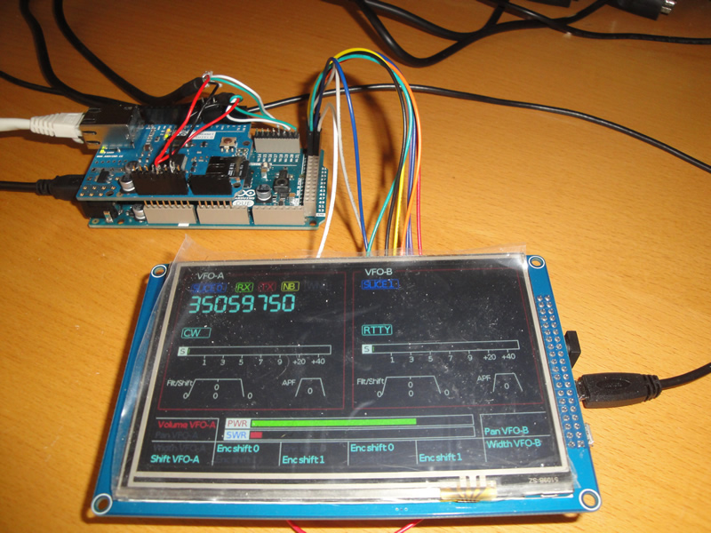 |
| The display working on a second Arduino (underneath the display). The 8-bit parallel interface wiring is clearly visible. |
I still have to implement data transfer in the opposite direction. It's not even slightly demanding, as the only traffic is touch screen transactions. A simple low speed serial interface will eat that problem without even pausing for breath.
So I have a solution, albeit at the cost of more hardware. Hardware is cheap, so that doesn't bother me but it would be nice to get to the bottom of this SPI problem!
19 March 2016
Size? Cost?
Malcolm, G3PDH posed a very interesting set of questions in comments on an earlier post, the answers to which justify a complete post in their own right. Malcolm said:
"I was a bit surprised to see that the envisaged cabinet size would be larger that a K3, so are you thinking of having the Flex 12v PSU in there too? I must say that my thoughts were along the lines of a supporting remote unit to give access to quick changes and for easily seeing where things were at but in parallel with using the main PC screen panadapter display. It would be a shame to lose that. Maybe you envisage just using the external box? Anyway, all very interesting. How do you see the final costing of such a unit compared to the Maestro?"
Here's some thoughts:
I selected the big case for the experimental version because it gives me plenty of room to work in as the project develops. As I envisage this being effectively my main station "radio on the desk" I wanted something big enough to have the controls nicely laid out (unlike the K3) and with a big enough cabinet that a large screen for the SmartSDR (SSDR) display, et al could be placed on top of it (unlike the Maestro). I am not short of room on my operating desk.
Of course the cabinet doesn't need to be anything like that big. In particular it needs almost no depth as it will be mostly empty inside. I have already had thoughts on a "Mini Flex Controller", which could be made as diminutive as you like, within reason. This could be used for, e.g. operation from a hotel room. The way I am writing the code should enable any physical layout to be be easily configured.
For example, one might decide to only have one VFO knob and a couple of encoders in a tiny box, doing everything else via the SSDR interface (you might as well buy the FlexControl in that case). At the other extreme you might have a big box with a huge screen and eight VFO knobs, one for each slice on a 6700. Same software in both cases.
So no, I am not defining the physical implementation, other than for this development system for my own personal use. At the moment no decision has been taken on whether or how the controller concept may be made available to other amateurs. If there is sufficient interest in the concept for me to make the code available then it will be up to each individual how he realises the physical implementation.
As for cost - well I expect this development machine to cost me as much if not more than a Maestro. But that's because I am buying all sorts of stuff to help with development work and so on. I suspect the cost to someone else would be dominated by how much they were willing to spend on the cabinet and finishing. Some people are content with any old hacked about panel and dymotape labels. You could do it quite cheaply in that case. I think the hardware costs, excluding cabinetry is no more than £100 or so.
17 March 2016
Bringing it all together
The good weather of the last few days has found me out doing other things, notably getting some serious flying in, so progress on the controller project has slowed somewhat. It's not been completely abandoned though and I've been working towards bringing all the component parts together into something approaching a complete system.
These are the principal components:
Now it is time to start bringing the various components together. A big step will be integrating the display subsystem with the encoder/VFO subsystems. This requires quite a lot of pin reassignment and some associated electronics to physically connect it all together. It also requires quite a lot of new software to connect up the Flex radio events to the display and to get the touch screen able to command the radio, etc. The controller software will now become quite complex, more completely resembling the final operational code. I suspect this work will take a few days.
I am also thinking about the physical implementation. There is likely to be a bit of a lead time in getting the front and rear panel CNC milling work done and getting them professionally painted/silk screened. My experience is that this effort is really very worthwhile, producing a controller that will be aesthetically pleasing as well as functionally capable.
I'm quite close now to running with the above layout. It is completely symmetrical, in effect providing controls for two complete transceivers in one box. This is really a follow on from my musings a few days ago that unlike most conventional radios, the Flex "slices" are identical radio invocations. It's not the end of the world if I decide down the line that I'd prefer a different layout but it's certainly harder to bash a lump of aluminium sheet than it is to change a chunk of software. So it seems like a good idea to stick to the old adage: measure twice, cut once.
I'll write some more when I've got progress to report on the subsystem integration work.
These are the principal components:
- Arduino Due microcomputer
- Ethernet interface "shield"
- Display subsystem & software
- Encoder subsystem & software
- VFO subsystem & software
- Switch multiplexer subsystem & software
- Ethernet hub
- Power supplies
Now it is time to start bringing the various components together. A big step will be integrating the display subsystem with the encoder/VFO subsystems. This requires quite a lot of pin reassignment and some associated electronics to physically connect it all together. It also requires quite a lot of new software to connect up the Flex radio events to the display and to get the touch screen able to command the radio, etc. The controller software will now become quite complex, more completely resembling the final operational code. I suspect this work will take a few days.
I am also thinking about the physical implementation. There is likely to be a bit of a lead time in getting the front and rear panel CNC milling work done and getting them professionally painted/silk screened. My experience is that this effort is really very worthwhile, producing a controller that will be aesthetically pleasing as well as functionally capable.
 |
| Is this the final panel layout? |
I'll write some more when I've got progress to report on the subsystem integration work.
13 March 2016
Switch multiplexers
One of the really satisfying things about a project like this is that it brings together a combination of hardware and software engineering. As an electronics engineer by training who moved into programming early in my career this is an ideal combination. It is fun to debug software using an oscilloscope on hardware that you constructed a few minutes earlier.
So I was looking forward to getting stuck into the switch multiplexer development that I alluded to a few posts ago. Having maxed out on software with the display project, it was good to plug the soldering iron in and wire up the multiplexer circuit to the Arduino. A very small amount of test software completed the package and it was time to test it out.
Nothing! Not a sausage. This is the point at which the 'scope got wheeled out. Effectively the software counts up in binary from 0 to 15 on four data lines to select the appropriate input. So the first thing was to hang the 'scope on these lines and look for square waves. There they were, exactly as expected. Still no mux output.
So I was looking forward to getting stuck into the switch multiplexer development that I alluded to a few posts ago. Having maxed out on software with the display project, it was good to plug the soldering iron in and wire up the multiplexer circuit to the Arduino. A very small amount of test software completed the package and it was time to test it out.
 |
| The switch mux test set up |
Nothing! Not a sausage. This is the point at which the 'scope got wheeled out. Effectively the software counts up in binary from 0 to 15 on four data lines to select the appropriate input. So the first thing was to hang the 'scope on these lines and look for square waves. There they were, exactly as expected. Still no mux output.
After rather longer than it should have taken me to think about it I took a closer look at the CD74HC4067 data sheet. Ahha! Chip select is low to enable and I had wired it to high. A silly mistake - all chip selects are low active but I was taken off down the wrong track by the lack of a bar over the CS legend.
 |
| Top trace is the mux selector MSB Lower trace is the switch 7 mux output |
Fixed that and the circuit more or less burst into life. With the 'scope I could see the appropriate switch line being selected and a nice square wave pulse into the Arduino with the correct timing for its mux slot.
In the photo you can see bit 3 of the mux input selector at the top trace. This is the most significant bit, so switches 0..7 are in the low period, 8..15 in the high period. One complete cycle of the mux inputs is one cycle of the square wave. The lower trace shows switch 7 pressed and the pulse turning up at exactly the right time for its mux slot.
Gibberish from the software though. All the odd numbered switch positions worked fine but #2 gave two switch returns, #4 gave four and #8 gave eight. Now this sounds like a timing problem related to binary transitions on the selector lines.
And so it turned out to be. It takes a little while for the mux to settle down, especially after several lines switch, such as the transition from 7 (0111) to 8 (1000). This was resulting in unstable output on the mux output line. It turned out to be very simple to fix - a delay of just 5us between setting the selector lines and reading the mux output is all that was required. Software and hardware working in perfect harmony!
So I now have the switch multiplexer working and can integrate that into the controller code. A satisfactory situation that calls for a minor celebration. I'm off to the pub!
Display developments
As it turned out I didn't fly on Friday as it was foggy and I quite like to be able to see where I am going. So I was able to spend some time working on the layout of the large LCD. There is a temptation to make this overly complex, an affliction not dissimilar to the tendency to put too many physical controls on the panel. I've probably not resisted too well on my first attempt.
Mainstream radios tend to treat the main and sub receivers differently, in part because they often are, in fact dissimilar technically. In the Flex, all receiver "slices" are created equal and so it seemed sensible to have identical screen layouts for each. It also makes the coding simpler. Along the top is a row of status indicators. I haven't yet decided whether these will also be touch buttons but there is no real reason why not.
Next comes the frequency, which I've chosen to display down to Hz, simply because that's what the Flex does. Under that is the mode indicator - again, this could be a touch button to bring up the mode selection menu. RIT and XIT indicators complete the line-up under the frequency. A bar type S meter follows and finally graphics representing the filter width, shift and APF settings. When a function or a VFO is inactive its display will be greyed out. You can see this in action with the VFO-A XIT and VFO-B RIT functions.
That seems like enough VFO stuff on the screen to me and the display, whilst reasonably full does not look too crowded. But I am more or less a 100% CW operator so I can imagine there are some things that need to be there for SSB/Data ops. What have I missed?
Below the VFO panels you can see the Tx power and SWR bar graphs and at the bottom of the screen is a key to the functions of the eight encoders. Each encoder has two states and you can see both of them, with the currently active one in cyan and the inactive one greyed out. This approach means that the encoders, which surround the lower part of the screen in the same layout, can be truly "soft". There is no need to place any function legends on the panel.
There is a surprising amount of code behind that screen layout! To some extent that is because the screen layout itself is soft - each component has its own set of dimension and position parameters in a look-up table that can be modified at will to make the screen layout anything we please.
I shall tweak the software a bit more before I integrate it into the Flex Controller code. It's much easier to play with it as a relatively small stand-alone program. Generally though, I am pleased with the way it's turned out. What do you think?
 |
| First stab at a suitable display layout |
Next comes the frequency, which I've chosen to display down to Hz, simply because that's what the Flex does. Under that is the mode indicator - again, this could be a touch button to bring up the mode selection menu. RIT and XIT indicators complete the line-up under the frequency. A bar type S meter follows and finally graphics representing the filter width, shift and APF settings. When a function or a VFO is inactive its display will be greyed out. You can see this in action with the VFO-A XIT and VFO-B RIT functions.
That seems like enough VFO stuff on the screen to me and the display, whilst reasonably full does not look too crowded. But I am more or less a 100% CW operator so I can imagine there are some things that need to be there for SSB/Data ops. What have I missed?
Below the VFO panels you can see the Tx power and SWR bar graphs and at the bottom of the screen is a key to the functions of the eight encoders. Each encoder has two states and you can see both of them, with the currently active one in cyan and the inactive one greyed out. This approach means that the encoders, which surround the lower part of the screen in the same layout, can be truly "soft". There is no need to place any function legends on the panel.
There is a surprising amount of code behind that screen layout! To some extent that is because the screen layout itself is soft - each component has its own set of dimension and position parameters in a look-up table that can be modified at will to make the screen layout anything we please.
I shall tweak the software a bit more before I integrate it into the Flex Controller code. It's much easier to play with it as a relatively small stand-alone program. Generally though, I am pleased with the way it's turned out. What do you think?
10 March 2016
Back to one Arduino
Earlier I discussed the issues I was finding with trying to implement a dual Arduino solution with the I/O devices on a separate microcomputer. Today I finished moving the code onto the main processor and at the same time I properly implemented the VFO logic so it is configured via the Profile file in the same way as the rotary encoders are. This means that the mapping between VFO knobs and slices is completely soft, as are parameters such as tuning speed.
Martin Lynch is a star! He has provided a couple of nice weighted VFO knobs which arrived today. It's amazing how something so simple brings the project to life: tuning felt strangely flat and uninspiring. With the weighted knobs the VFOs spin up and down the band perfectly. I do like a decent flywheel action and this is now even better than my old FT1000D was years ago. One quick flick and off up the band we go!


Above you can see the VFO-A & VFO-B encoders decked out with their spinner knobs. The right hand picture shows the development system as of today, with just the single Arduino, a pair of rotary encoders and the two VFO encoders, as well as the old display, which is displaying actual Flex information, and the new display, which is not... yet.
Which brings me neatly on to the results of bringing the VFOs and encoders onto the main processor. What a difference! All the lag has disappeared and the tuning feels just like a "proper" radio. The combination of this software change and the weighted VFO knobs is something I feel I can be entirely happy with.
Tomorrow is a flying day and it's BERU, sometimes referred to as the Commonwealth contest over the weekend, so there probably won't be a lot of progress to report until early next week.
Martin Lynch is a star! He has provided a couple of nice weighted VFO knobs which arrived today. It's amazing how something so simple brings the project to life: tuning felt strangely flat and uninspiring. With the weighted knobs the VFOs spin up and down the band perfectly. I do like a decent flywheel action and this is now even better than my old FT1000D was years ago. One quick flick and off up the band we go!
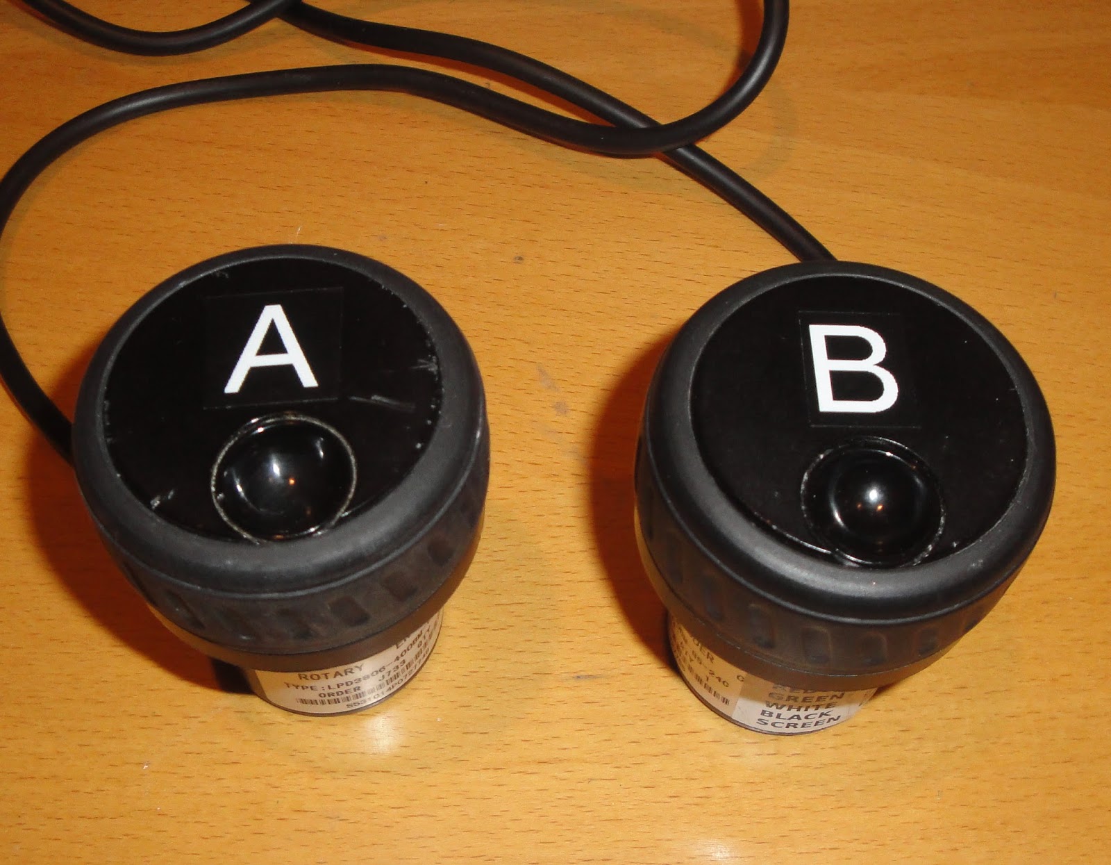

Above you can see the VFO-A & VFO-B encoders decked out with their spinner knobs. The right hand picture shows the development system as of today, with just the single Arduino, a pair of rotary encoders and the two VFO encoders, as well as the old display, which is displaying actual Flex information, and the new display, which is not... yet.
Which brings me neatly on to the results of bringing the VFOs and encoders onto the main processor. What a difference! All the lag has disappeared and the tuning feels just like a "proper" radio. The combination of this software change and the weighted VFO knobs is something I feel I can be entirely happy with.
Tomorrow is a flying day and it's BERU, sometimes referred to as the Commonwealth contest over the weekend, so there probably won't be a lot of progress to report until early next week.
Display
The slow boat from Hong Kong finally delivered by TFT colour screen today so I just had to play! These things come with quite excellent libraries so it is fairly easy to create simple display layouts quite quickly. Before long I had a VFO-A/VFO-B display running (no live data yet, just static text).
Although programming the screen is quite straightforward, getting everything laid out nicely is going to be a challenge and will require a fair bit of code. I shall develop the display software separately to begin with, as it makes the code/test/debug cycle much quicker.
The screen is touch sensitive, so I spent a bit of time playing with this as well. It's a bit of a sod to set up but once that's done properly it works just fine. I can foresee the touch screen being used for menu selection activities such as band selection. I think it's less likely that I would consider it as a replacement for twiddly things.
Anyway, it's good to have the final major system component to hand and I think that development should be able to progress quite quickly now. There's still a lot to do...
 |
| The colour 800px X 600px touch screen |
The screen is touch sensitive, so I spent a bit of time playing with this as well. It's a bit of a sod to set up but once that's done properly it works just fine. I can foresee the touch screen being used for menu selection activities such as band selection. I think it's less likely that I would consider it as a replacement for twiddly things.
Anyway, it's good to have the final major system component to hand and I think that development should be able to progress quite quickly now. There's still a lot to do...
8 March 2016
Encoders encoding
As I discussed in my posting last night, I spent some time today connecting up all the various data arrays with code. It's all working now, which is a significant chunk of progress, as I now have an end-to-end, profile configured system for the encoders. The same principle can now be applied to the push buttons and the VFO controls. In the latter case it's perhaps less of a valuable exercise, although the thought did occur to me as I was working on the code that the VFO controls could be made configurable to operate any of the Flex "slices" using the same technique. Whether that is particularly useful is a moot point.
I can now build on this code by implementing all 43 Flex control functions. So far I've only done four: audio gain, audio pan, filter width and filter shift. Essentially the others are just minor variations on one or other of the ones I've already done.
What to do about those push buttons?
Hitherto, I've been faffing around with a dual Arduino configuration linked by a serial port. It sounds like a nice idea in principle, providing huge scope for enhancement. But there the benefits end. I'm finding that the controls, notably the VFOs are sluggish in response and after a lot of analysis work I've concluded that the issue is the large number of tasks that the dual processor approach dictates must be done sequentially.
So I'm back to trying to squeeze everything into a single Arduino. There should be no problem with processing power but connectivity is marginal. Each encoder needs three input pins and the display unit gobbles up a massive chunk of 25 pins its wonders to perform. Even with the considerable connectivity of the Arduino Due, it's a bit of a challenge.
My original design called for each of the 16 push buttons to be assigned its own pin and interrupt. Whilst this is simple to implement it's a ridiculously inefficient way to handle an I/O device that may be pushed once in a while. The answer, of course, is to multiplex them. 16 is a handy number from that point of view, because the exceptionally flexible CD74HC4067 is a 16 pin multiplexer. Four address lines are used to select 1 of 16 and a single pin receives the button status. Sixteen pins reduced to five is a good start!
Using the CD74HC4067 approach leaves me just one pin short of what I need. I could explore multiplexing some of the encoders (not the VFOs!) but I'd rather like to avoid that complexity if I can. So I'm on the war path, looking for a pin that I can save from some other task. *
In other news, the equipment case arrived today, so I can start working on panel design in earnest. Still waiting for the slow boat from Hong Kong to deliver my display unit. When that turns up I should have pretty well everything I need to finish the project design. There's still a long way to go.
* As I was writing this Blog entry the solution came to me, proving once again that it is often the act of writing things down that focusses the mind! Each encoder has a built in push button and there is no reason at all why these 8 buttons should not be multiplexed. That saves me 8 input pins, at the expense of one more multiplexer input pin. At a stroke I have six spare pins in my single Arduino implementation. Game on!
7 March 2016
Soft panel ideas
It was a beautiful day today, so I have to report, dear reader, that I abandoned the Flex controller project and went flying. Very pleasant it was too, with the snow capped mountains contrasting strongly with an azure blue sky. I never forget just how lucky I am to be able to pursue such a wonderful hobby.
Back slaving over a fast computer this evening, I've been cogitating about how the panel will be configured. Ideally, every control on the panel can be software configured to perform any function (within reason - it wouldn't make much sense configuring a push button switch as the main VFO!). To do this needs various interconnected data structures and would make a neat database application if the controller were running on a PC. In this case there is no database, so it has to be done from first principles.
There are eight Encoders, each of which can have two control states by use of its built in push-button. There are thus up to 16 "things" that we can control. Each encoder is mapped to the required control via a lookup table, which is where the ability to reconfigure the panel is implemented.
There are thus 16 controls, each of which will have a number of attributes:
With this general layout in mind I could turn my mind to devising a profile file layout. Purists will say that this ought to be in XML or JSON or some such but this is not going anywhere else, so a simple text file will suffice. At the moment I am editing the file manually but in the fullness of time I would expect to be able to construct profiles from the controller in some way. Maybe. The file is held on a micro SD card that plugs into the Arduino system. Slight overkill: the SD card is 16GB and the profile files will be about 4kB each. I will probably find some other stuff to stick on there...
Next, I devised the data structures that will be required by the Arduino to do its thing. The profile file is used to set these structures, effectively mapping physical controls to a Flex control function. This bit has taken a few iterations and I am not certain that it is optimised yet. Whilst the Adruino Due has a reasonable amount of program/data space (512kB) I do not have the luxury of being able to have inefficient data structures.
This evening I've written the code to read in the profile file and set the data structures accordingly. Yet to do, is to join all these bits up in code, so this particular encoder commands that specific Flex function. A job for tomorrow.
For now I have only dealt with the eight encoders. I'll let this settle down and get the bugs (of which I suspect there will be many!) fixed before tackling the push-button logic. My intention is that the buttons should similarly be a "soft" as possible.
Getting this part of the design right is an important step towards achieving a truly configurable panel.
Back slaving over a fast computer this evening, I've been cogitating about how the panel will be configured. Ideally, every control on the panel can be software configured to perform any function (within reason - it wouldn't make much sense configuring a push button switch as the main VFO!). To do this needs various interconnected data structures and would make a neat database application if the controller were running on a PC. In this case there is no database, so it has to be done from first principles.
There are eight Encoders, each of which can have two control states by use of its built in push-button. There are thus up to 16 "things" that we can control. Each encoder is mapped to the required control via a lookup table, which is where the ability to reconfigure the panel is implemented.
There are thus 16 controls, each of which will have a number of attributes:
- Name (so it can be referenced on screen, etc.)
- Enabled/disabled
- Current value
- Maximum value
- Minimum value
- Step up/down per "click"
- Update flags
- Owner slice (a slice is effectively a complete Rx/Tx. The Flex 6500 has four)
- Flex control function (what we actually want to do to the Flex radio)
With this general layout in mind I could turn my mind to devising a profile file layout. Purists will say that this ought to be in XML or JSON or some such but this is not going anywhere else, so a simple text file will suffice. At the moment I am editing the file manually but in the fullness of time I would expect to be able to construct profiles from the controller in some way. Maybe. The file is held on a micro SD card that plugs into the Arduino system. Slight overkill: the SD card is 16GB and the profile files will be about 4kB each. I will probably find some other stuff to stick on there...
Next, I devised the data structures that will be required by the Arduino to do its thing. The profile file is used to set these structures, effectively mapping physical controls to a Flex control function. This bit has taken a few iterations and I am not certain that it is optimised yet. Whilst the Adruino Due has a reasonable amount of program/data space (512kB) I do not have the luxury of being able to have inefficient data structures.
This evening I've written the code to read in the profile file and set the data structures accordingly. Yet to do, is to join all these bits up in code, so this particular encoder commands that specific Flex function. A job for tomorrow.
For now I have only dealt with the eight encoders. I'll let this settle down and get the bugs (of which I suspect there will be many!) fixed before tackling the push-button logic. My intention is that the buttons should similarly be a "soft" as possible.
Getting this part of the design right is an important step towards achieving a truly configurable panel.
5 March 2016
Panel prognostications
I've spent most of today doing other things! Yes, it had to happen: there are other things to life than Flex controllers.
Needless to say I'm back on the case now and have spent an hour or so thinking about the physical implementation of my controller. I've ordered what I hope will be a suitable instrument case and whilst I await Monday's delivery have put some thought into the front panel layout. The panel is 134mm x 367mm (5.3" x 14.5") which seems to be about the right size for all the controls I will ever need.
I reckon it's going to end up looking something like this. To the left I've added a power switch and microphone, headphone and keyer sockets. The band select pad is gone, replaced by a single button that will bring up a virtual band keypad on the touch screen. The group of eight buttons above VFO-B are unassigned, which means they can be used for anything that takes my fancy further down the line. I'm not really convinced there is a need for them but there's a bit of vacant space there above the VFO knob without them. If I think of anything else to go there the buttons may well be deleted!
This design gives me eight multifunction encoders that can be assigned by software to anything I want. Each encode has a built in push-switch which can act as a shift function, potentially giving me 16 encoders. I feel sure that will be quite sufficient!
Internally, there won't really be all that much beyond the front panel controls, the screen and a bunch of wires. I think there will be more than enough room for these items:
So I now await the arrival of the instrument case on Monday to finalise dimensions and build a full-size mock up with bits of cardboard. There will probably be a few more iterations along the way but eventually I'll produce a PostScript cutting file and take it to a local mate who has a CNC milling machine with which to cut the panel. My plan then is to have the panel painted at my local vehicle paint shop and silk screened with appropriate legends for what should be a reasonably professional result.
Somehow I just know that all this is going to end up costing me more than just splurging out on a Maestro but I think I'm having more fun this way!
Needless to say I'm back on the case now and have spent an hour or so thinking about the physical implementation of my controller. I've ordered what I hope will be a suitable instrument case and whilst I await Monday's delivery have put some thought into the front panel layout. The panel is 134mm x 367mm (5.3" x 14.5") which seems to be about the right size for all the controls I will ever need.
 |
| The Mark II panel layout, now with deleted buttons! |
This design gives me eight multifunction encoders that can be assigned by software to anything I want. Each encode has a built in push-switch which can act as a shift function, potentially giving me 16 encoders. I feel sure that will be quite sufficient!
Internally, there won't really be all that much beyond the front panel controls, the screen and a bunch of wires. I think there will be more than enough room for these items:
- Arduino Due Control processor, with Ethernet controller
- Arduino Due I/O processor
- Four port Ethernet switch
- 5V power supply unit
- WinKey or similar and sidetone generator
So I now await the arrival of the instrument case on Monday to finalise dimensions and build a full-size mock up with bits of cardboard. There will probably be a few more iterations along the way but eventually I'll produce a PostScript cutting file and take it to a local mate who has a CNC milling machine with which to cut the panel. My plan then is to have the panel painted at my local vehicle paint shop and silk screened with appropriate legends for what should be a reasonably professional result.
Somehow I just know that all this is going to end up costing me more than just splurging out on a Maestro but I think I'm having more fun this way!
Saturday status
Things are moving along quite well, somewhat to the detriment of other things I really ought to be doing, like getting on the air or going flying. That's how I tend to operate in the early stages of a project: all or nothing!
Yesterday I got the filter width and shift control logic working. This turned out to be more tricky than I expected because the Flex allows you to do silly things that you would never want to do in practice. In this case simply increasing the width eventually results in the lower edge of the passband moving through the zero beat point and on up the other sideband. This is unlikely to be what we wanted. So I devised some logic to extend the filter edges symmetrically until the LF edge reaches zero beat and from then on only extend the HF edge.
The pictures show, respectively, bandwidths of 600Hz, 1200Hz, 2000Hz (showing asymmetric edges) and finally, 1000Hz shifted HF by 700Hz, all as selected by my controller. They also show what a rather wide CW signal looks like on the waterfall. I've seen far worse!


The controls work very well and are impressive in use but I can already see that all I've done is fix a single invocation of the problem - USB CW. LSB CW will require the logic to be reversed and USB/LSB single sideband will require yet another approach that I'll have to think about carefully. Not being an SSB op, this might be rather low priority.
Shift, by comparison was easy to implement and is, again, quite good fun to play with. The two controls together make it easy to explore the Flex radio's filter performance, which is, to say the least, impressive.
As reported earlier, I determined the cause of the VFO tuning crash but have done nothing more than note it in my project To Do list for now. I have also given more thought to panel layout and the physical control requirements, which I have decided can be simplified somewhat.
By now I feel that I am reaching the point at which proof of concept has been achieved. There is still a lot more software to write (I doubt I've done 5% of it yet) but there should be no major new concepts that need to be designed and debugged. I feel that I know how to drive the Flex API now, so most of the work to come will be concerned with making the panel interface highly configurable. I also have to learn how to program the display but I can't start on that until the slow boat from Hong Kong arrives at these shores.
So I think I am now on to physical implementation issues - panel layout in particular. I have some important decisions to make on the type and shape/size of cabinet. Bigger than a K3 but a lot smaller than an FT5000 I think. I shall be writing more about this over the weekend... stay tuned.
Finally, I have to report, I accidentally made a QSO with the Flex yesterday, in the middle of testing some software. I was tuning around 20m and came across TI5/N4YDU who was a colossal signal and rattling along at 30 WPM plus. One call and I was in the log and had broken my duck with the Flex 6500. It's nice to know that the radio does, in fact, make QSOs...
Yesterday I got the filter width and shift control logic working. This turned out to be more tricky than I expected because the Flex allows you to do silly things that you would never want to do in practice. In this case simply increasing the width eventually results in the lower edge of the passband moving through the zero beat point and on up the other sideband. This is unlikely to be what we wanted. So I devised some logic to extend the filter edges symmetrically until the LF edge reaches zero beat and from then on only extend the HF edge.
The pictures show, respectively, bandwidths of 600Hz, 1200Hz, 2000Hz (showing asymmetric edges) and finally, 1000Hz shifted HF by 700Hz, all as selected by my controller. They also show what a rather wide CW signal looks like on the waterfall. I've seen far worse!
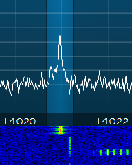


The controls work very well and are impressive in use but I can already see that all I've done is fix a single invocation of the problem - USB CW. LSB CW will require the logic to be reversed and USB/LSB single sideband will require yet another approach that I'll have to think about carefully. Not being an SSB op, this might be rather low priority.
Shift, by comparison was easy to implement and is, again, quite good fun to play with. The two controls together make it easy to explore the Flex radio's filter performance, which is, to say the least, impressive.
As reported earlier, I determined the cause of the VFO tuning crash but have done nothing more than note it in my project To Do list for now. I have also given more thought to panel layout and the physical control requirements, which I have decided can be simplified somewhat.
By now I feel that I am reaching the point at which proof of concept has been achieved. There is still a lot more software to write (I doubt I've done 5% of it yet) but there should be no major new concepts that need to be designed and debugged. I feel that I know how to drive the Flex API now, so most of the work to come will be concerned with making the panel interface highly configurable. I also have to learn how to program the display but I can't start on that until the slow boat from Hong Kong arrives at these shores.
 |
| A possible enclosure for my Flex controller |
Finally, I have to report, I accidentally made a QSO with the Flex yesterday, in the middle of testing some software. I was tuning around 20m and came across TI5/N4YDU who was a colossal signal and rattling along at 30 WPM plus. One call and I was in the log and had broken my duck with the Flex 6500. It's nice to know that the radio does, in fact, make QSOs...
4 March 2016
VFO encoder vicissitudes
Warning: Techy Stuff!
The VFO encoders I have chosen (at least for starters) are 400 pulse/revolution optical units. Like all encoders, these have two square wave outputs, the phase relationships of which determine the direction of rotation. On the face of it, it's an easy task to interrupt on state changes, read the two outputs, do a state table lookup to determine the direction of travel and post a CW/CCW transaction. And that's exactly what I have done.
The code works just fine until you jerk the VFO knob suddenly. At this point the Arduino dies and only comes back to life with a reset. It's fairly obvious that the problem is due to state changes happening too quickly for something to cope with. The question is what.
To put this in context, let's look at some numbers. The encoder actually produces four level transitions (interrupts) for each step. So that's 1600 in 360 degrees. Let's say I can jerk the VFO knob at a rate equivalent to 10 RPM (not sure if I can but it's probably not far out). So that's 16,000 interrupts/second or one every 62.5uS. Hmm that's actually quite quick but surely the ARM-based Arduino Due can handle that?
Well it turns out that it cannot. After a lot of experimenting, I've discovered that the Arduino digitalRead() instruction, which one might expect to take a microsecond or so can actually take up to 70uS. This in turn is because a whole load of code has to be executed to handle the different pin assignments on various different models of Arduino.
I was surprised by this apparent inefficiency and did some research of my own. The Arduino has a micros() function that enables one to see how many microseconds have elapsed. It is thus a simple matter to measure how long any section of code is taking. Sure enough, the digitalRead instructions are the problem. I'm guessing that the digitalRead code is not re-entrant and the next interrupt comes along, re-entering the digitalRead code before the previous read has completed. Not very good programming practice!
There is a solution. It is possible to directly read the I/O pins using low level code and that will be very much faster. It's not device independent code any more but that doesn't matter as I do not plan to be changing processor boards once the project is completed.
I'm probably going to leave a decision on this until later to see whether it's an issue in practice but I thought it was quite an interesting problem to contemplate. I am sure there will be many more.
More panel thoughts
I'm beginning to think that there is a temptation to put too many controls on my panel! Yes, I realise that this is a contradiction in many ways but it seems to me that some sort of balance needs to be struck between making frequently used controls easily available and having a physical control for everything you might ever want to change. Consider this early layout proposal, in which the small squares are push buttons and the large squares are rotary encoders.
I am taking it as a given that I want VFO-A and VFO-B knobs. I also like the idea of a large colour display screen that can be used to show any radio parameters I like, including panadapter/waterfall displays. So with those as a given, the task at hand is to fit the other controls around them in an ergonomically sound fashion.
So what do I really need to be able to do quickly? Well certainly VFO tuning, audio level, filter settings and assignment of Tx/Rx functions to each VFO (split operation, etc.). That accounts for the big knobs, a few rotary encoders and a few push buttons. And the display, of course.
To the right of the display is a keypad of 12 buttons. No prizes for guessing what they are intended for - they are the band select buttons. They use up quite a bit of panel real estate. How often do I change bands? Well quite often actually, but frequently that's under the control of my logging program, as a result of clicking on a spot. Other times I might be chasing some DX (or an FOC member in the Marathon) up the bands, so reasonably quick QSYs are a good thing. But does it need a field of physical buttons?
My chosen display, currently on the slow boat from Hong Kong, is a 5" (diagonal) touch screen. Perhaps a better option would be to have a single band select button that brings up a touch pad on the screen? One physical button instead of 12. And, importantly, the ability to easily add more touch pad buttons should, for example, a new band materialise one day.
Another thing to consider is that the physical panel is one part of a project that will let me try out various virtual panel layouts, simply by changing the software. That tends to argue for fewer, more critical, physical controls and greater use of the touch screen for other functions. It might also argue for a bigger touch screen.
Getting the balance right between ease of use/ergonomically sound layout and the temptation to replicate an entire FT5000 panel in hardware is going to be a bit of a challenge!
 |
| First attempt at the physical panel layout |
I am taking it as a given that I want VFO-A and VFO-B knobs. I also like the idea of a large colour display screen that can be used to show any radio parameters I like, including panadapter/waterfall displays. So with those as a given, the task at hand is to fit the other controls around them in an ergonomically sound fashion.
So what do I really need to be able to do quickly? Well certainly VFO tuning, audio level, filter settings and assignment of Tx/Rx functions to each VFO (split operation, etc.). That accounts for the big knobs, a few rotary encoders and a few push buttons. And the display, of course.
To the right of the display is a keypad of 12 buttons. No prizes for guessing what they are intended for - they are the band select buttons. They use up quite a bit of panel real estate. How often do I change bands? Well quite often actually, but frequently that's under the control of my logging program, as a result of clicking on a spot. Other times I might be chasing some DX (or an FOC member in the Marathon) up the bands, so reasonably quick QSYs are a good thing. But does it need a field of physical buttons?
 |
| The proposed display unit |
My chosen display, currently on the slow boat from Hong Kong, is a 5" (diagonal) touch screen. Perhaps a better option would be to have a single band select button that brings up a touch pad on the screen? One physical button instead of 12. And, importantly, the ability to easily add more touch pad buttons should, for example, a new band materialise one day.
Another thing to consider is that the physical panel is one part of a project that will let me try out various virtual panel layouts, simply by changing the software. That tends to argue for fewer, more critical, physical controls and greater use of the touch screen for other functions. It might also argue for a bigger touch screen.
Getting the balance right between ease of use/ergonomically sound layout and the temptation to replicate an entire FT5000 panel in hardware is going to be a bit of a challenge!
3 March 2016
Early panel thoughts
So with all this nonsense of wanting to design my own control panel, just what are the controls that I feels are so important to have? Here's my list for starters:
- Separate VFO-A and VFO-B knob. Nice big weighty ones, like you get on proper radios(!)
- A decent display that shows all the stuff I am interested in for at least two radios. The 6500 can do up to four... could be a challenge.
- Separate volume encoders for A & B
- Filter width and shift encoders for A & B
- A couple of spare encoders that can be assigned to things like notch, noise blanker, etc.
- A band select key pad
- A bunch of other push buttons for various things such as split/simplex, mode selection, et al
- VFO-A & VFO-B LED buttons, a la FT5000, for quick control of which VFO does what
Getting started
When I discovered the Flex Radio Maestro I realised that there was a new paradigm in town. In many respects the Maestro is exactly what I was looking for, on two counts - It is a proper panel with a decent stab at the sort of controls I feel I would want but much more importantly, it validated the concept of an SDR with a network-connected full panel.
I could have gone for the Maestro but I am an inveterate experimenter and derive great satisfaction out of devising mixed hardware/software solutions to awkward problems. So I was drawn to explore the Flex Radio Application Programming Interface (API) in more detail.
Very quickly I came across Endo, IW7DMH's excellent web site. Wow! Endo has done more or less exactly what I had been thinking of. Not only that but he has written a large body of public domain software to present the Flex API as an interface to Arduino-based processors. A sort of an API on top of an API, if you like. I have done quite a lot of work with Arduinos in the past, so this seems perfect.
I have a couple of Arduino processors kicking around the place in need of a project, so I started writing some code to get an idea of how Endo's API on an API works. It turns out to be quite straightforward and even my rusty C skills soon produced results. Next, I started thinking about the major problem areas for the hardware and quickly came up against the need for high quality high resolution rotary encoders for the VFOs. It's possible to spend a lot of money but I soon found these at a very respectable price. A few days later they'd arrived and I was off writing code again!
By now the lack of a Flex radio was starting to become something of an issue. Martin Lynch came to the rescue in exchanged for a large wad of used notes (well... a severe dent in my credit card, to be more accurate) and less than 18 hours later I was unwrapping my new Flex 6500. Within an hour of switching it on I had one VFO control working (sort of - but it proved the concept). I might be the only radio amateur ever whose immediate reaction to the arrival of a new radio is to start writing software for it!
A few days later and I have both VFOs working and, for the most part, debugged. I have a rudimentary display and one shaft encoder, currently programmed as the volume control, sprawled across my desk.
As you can see, there are in fact now two Arduinos! Well that's what happens when you decide that you want loads of I/O - you run out of pins. So the control Arduino, with the networking card, does all the interface work to the Flex 6500 and also drives the display, a basic character display at the moment, but will eventually be a 5" colour touch-screen.
The other Arduino handles the boring stuff of providing connectivity to all the encoders, switches, LEDs and so on that will festoon the front panel of my controller. The two Arduinos communicate with one-another using serial I/O and a simple protocol than I have devised to keep data transfers as short as possible. All this is working well.
So things are coming along quite nicely. I feel that I am nearing the proof of concept point now, so it's time to start thinking about panel layouts and other implementation details.
I could have gone for the Maestro but I am an inveterate experimenter and derive great satisfaction out of devising mixed hardware/software solutions to awkward problems. So I was drawn to explore the Flex Radio Application Programming Interface (API) in more detail.
Very quickly I came across Endo, IW7DMH's excellent web site. Wow! Endo has done more or less exactly what I had been thinking of. Not only that but he has written a large body of public domain software to present the Flex API as an interface to Arduino-based processors. A sort of an API on top of an API, if you like. I have done quite a lot of work with Arduinos in the past, so this seems perfect.
I have a couple of Arduino processors kicking around the place in need of a project, so I started writing some code to get an idea of how Endo's API on an API works. It turns out to be quite straightforward and even my rusty C skills soon produced results. Next, I started thinking about the major problem areas for the hardware and quickly came up against the need for high quality high resolution rotary encoders for the VFOs. It's possible to spend a lot of money but I soon found these at a very respectable price. A few days later they'd arrived and I was off writing code again!
By now the lack of a Flex radio was starting to become something of an issue. Martin Lynch came to the rescue in exchanged for a large wad of used notes (well... a severe dent in my credit card, to be more accurate) and less than 18 hours later I was unwrapping my new Flex 6500. Within an hour of switching it on I had one VFO control working (sort of - but it proved the concept). I might be the only radio amateur ever whose immediate reaction to the arrival of a new radio is to start writing software for it!
 |
| A snippet of Arduino code |
 |
| I think this is what they call a lash-up |
The other Arduino handles the boring stuff of providing connectivity to all the encoders, switches, LEDs and so on that will festoon the front panel of my controller. The two Arduinos communicate with one-another using serial I/O and a simple protocol than I have devised to keep data transfers as short as possible. All this is working well.
So things are coming along quite nicely. I feel that I am nearing the proof of concept point now, so it's time to start thinking about panel layouts and other implementation details.
Twenty years later...
I've been a Yaesu man since I could first afford to buy commercial amateur radio kit some time back in the '70s. Yaesu produced some pretty good radios and, frankly, some terrible ones, notably in the early synthesiser days. Yaesu weren't alone in this - most early synthesiser radios were pretty poor. In the end I found what I needed and Yaesu started getting their synthesiser radios to work properly. Starting with an FT1000D (excellent radio, wish I'd kept it!) through the FT1000MP and FT1000 Mk V, I eventually moved on to the FT5000 when they first appeared around five years ago.
Generally, I've been happy with the FT5k. It has some annoying aspects (notably the lack of a fixed stereo audio output for recording QSOs) but in general it's a fine radio. After fiver years I might reasonably be expected to be eyeing up what's coming next but, in general the answer has been "nothing that's good enough to displace the FT5k". As mentioned in my initial post, I continued to discount SDRs even though, from a technical point of view they appeared to be coming along well and were, by now, knocking on the performance doors of top of the range radios.
A chance exchange of e-mails on the CDXC reflector in February 2016 changed all that.
Steve, G1XOW, who is an SDR aficionado and is quite content with mouse clicking his way around the bands, helped me to realise that SDR does not equal no control panel with twiddly knobs and buttons to press. Of course I sort of knew that already - even the Pegasus had an optional external VFO knob - but none of the bolt-on goodies seemed to address the broader issue of a full panel.
The key discovery was that Flex Radio Systems were producing just such a control panel - the Maestro. Interesting! Form factor-wise the Maestro doesn't do it for me but it made me realise that it must now be possible to fully control an SDR via an external interface. The question was "is that interface specification available?" The answer, it turns out, is yes. Not only that but it is fully open source and the interface is via Ethernet, so it's easy to implement.
By degrees, a cunning plan began to emerge. I could build my own custom panel!
And so we come to the purpose of this Blog, as I navigate the route from this simple idea to something that meets my, admittedly demanding, requirements. If I get it right then never again shall I need to complain about the ergonomics of my radio, for I shall have it in my power to make it as I wish it to be. If it works then I shall have that worthy successor to the FT5000 that has eluded me hitherto.
Feel free to join me for the ride.
Generally, I've been happy with the FT5k. It has some annoying aspects (notably the lack of a fixed stereo audio output for recording QSOs) but in general it's a fine radio. After fiver years I might reasonably be expected to be eyeing up what's coming next but, in general the answer has been "nothing that's good enough to displace the FT5k". As mentioned in my initial post, I continued to discount SDRs even though, from a technical point of view they appeared to be coming along well and were, by now, knocking on the performance doors of top of the range radios.
A chance exchange of e-mails on the CDXC reflector in February 2016 changed all that.
Steve, G1XOW, who is an SDR aficionado and is quite content with mouse clicking his way around the bands, helped me to realise that SDR does not equal no control panel with twiddly knobs and buttons to press. Of course I sort of knew that already - even the Pegasus had an optional external VFO knob - but none of the bolt-on goodies seemed to address the broader issue of a full panel.
 |
| The Flex Radio Maestro |
By degrees, a cunning plan began to emerge. I could build my own custom panel!
And so we come to the purpose of this Blog, as I navigate the route from this simple idea to something that meets my, admittedly demanding, requirements. If I get it right then never again shall I need to complain about the ergonomics of my radio, for I shall have it in my power to make it as I wish it to be. If it works then I shall have that worthy successor to the FT5000 that has eluded me hitherto.
Feel free to join me for the ride.
In the beginning
Welcome to my Flex radio controller Blog.
There's a lot of interest these days in Software Defined Radios (SDR). To a certain extent pretty well all modern radios are software defined, so we'd better get some sort of starting point established here. For the purposes of this Blog, I define a SDR as one where the radio signal is converted directly to/from baseband. The technical term is Direct Down Conversion for Rx/Direct Up Conversion for Tx (DDC/DUC). The Flex 6000 series are examples of DDC/DUC transceivers.
 I dabbled briefly in the SDR world about 20 years ago when such things were in their infancy. The radio was a Ten Tec Pegasus and, in many ways it was quite revolutionary. It suffered from the lack of processing power in that era but it was still not a bad radio by any means. The experience of controlling a radio via mouse and keyboard wasn't particularly satisfying and in the end the Pegasus and I parted company.
The Pegasus, in common with most SDRs is just a black box with a few connectors - no panel controls at all. And here we come up against a rather strange piece of received wisdom, namely that SDRs just don't - and by implication can't - have traditional control panels. The implication is that one can have a hybrid (mixed analogue and DSP radio) with a panel or a SDR without a panel. This apparent "fact" is, in part, perpetuated by SDR aficionados who perceive some sort of unique selling point in the very idea that an SDR should indeed not have a physical control panel.
That's all well and good but, to my mind at least, with some 50+ years of knob twiddling amateur radio to my name, it is wrong. The agility in pileups and contests that is provided by separate VFO-A and VFO-B knobs, instant access to bandwidth, notch, noise blanker and volume controls cannot be matched when your sole input device is a mouse.
And so I continued with "traditional" radios, convinced in my own mind that SDR was ergonomically a bad thing. Until recently...
There's a lot of interest these days in Software Defined Radios (SDR). To a certain extent pretty well all modern radios are software defined, so we'd better get some sort of starting point established here. For the purposes of this Blog, I define a SDR as one where the radio signal is converted directly to/from baseband. The technical term is Direct Down Conversion for Rx/Direct Up Conversion for Tx (DDC/DUC). The Flex 6000 series are examples of DDC/DUC transceivers.

The Pegasus, in common with most SDRs is just a black box with a few connectors - no panel controls at all. And here we come up against a rather strange piece of received wisdom, namely that SDRs just don't - and by implication can't - have traditional control panels. The implication is that one can have a hybrid (mixed analogue and DSP radio) with a panel or a SDR without a panel. This apparent "fact" is, in part, perpetuated by SDR aficionados who perceive some sort of unique selling point in the very idea that an SDR should indeed not have a physical control panel.
That's all well and good but, to my mind at least, with some 50+ years of knob twiddling amateur radio to my name, it is wrong. The agility in pileups and contests that is provided by separate VFO-A and VFO-B knobs, instant access to bandwidth, notch, noise blanker and volume controls cannot be matched when your sole input device is a mouse.
And so I continued with "traditional" radios, convinced in my own mind that SDR was ergonomically a bad thing. Until recently...
Subscribe to:
Posts (Atom)